So, I was binging YouTube and stumbled across this video about sprag clutches. You can think about them as one-way bearings - the shaft will freely rotate in one direction, but is coupled to the outer rim in the other.
I then found a couple designs of these clutches on Thingiverse and GrabCAD and went ahead and printed a couple (PLA). This one printed the best, but I decided to make my own to play around with the tolerances.
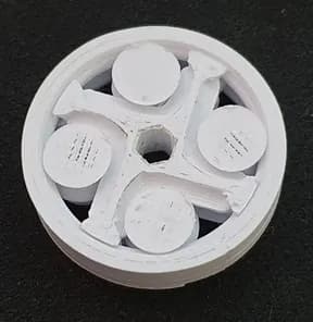
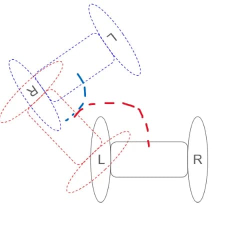
Basically, how these printed ones work is that in one direction, the geometry jams the inner ‘tapered cylinders’ in one direction only due to the angled arrangement of the 4 arms. Then sprung the idea of making a single DoF robot that can traverse a 2D landscape by a ‘waddling’ like motion. If a motor body is attached to one bearing, and the shaft to another, taking each bearing to be a wheel of sorts, then the robot can pivot across each wheel. The drawing below is a trajectory the robot can take.
Here’s a simple setup demonstrating the bot. I added some rubber bands for traction. As you can see, there is still a ton of work to be done for optimizing the wheel performance to reduce slippage.
Maybe I’ll get back to this someday! Schoolwork is cooking me right now 0_0.
Ok bye.