Hola peepsicles! So, a lot of what I was learning about this past summer revolved around optimizing circuit topology with respect to thermal noise. See this post for a function I implemented to calculate the thermal noise of any circuit at any node.
To verify my understanding on subject matter, I compiled a ‘lecture note’ on Harry Nyquist’s 1928 paper: Thermal Agitation of Electric Charge in Conductors. I think it’s a pretty elegant derivation, so here ya go!
Table of Contents
Open Table of Contents
Motivation
Dr. Johnson experimentally discovered fluctuations of voltage noise across a resistor due to thermal agitation. Electrons within a conductor oscillate due to thermal energy, and thus, produce voltage noise across the resistor. This lecture note will derive the voltage noise as a function of temperature and resistance using principles from thermodynamics and circuit theory.
Noise Dependence on T & R
Let’s assume that resistor generates some voltage noise when in a thermal bath of temperature . From the second law of thermodynamics, we know that no power can be extracted from produced voltage noise, since the temperature of the load is equal to the temperature of the resistor.
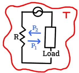
Thus, the power dissipated in the load from the resistor is equal to the power dissipated in the resistor from the load. From this reasoning, we see that a thermal bath can only generate a voltage noise if the circuit object is capable of dissipating energy. Thus, only resistors can produce noise, while ideal inductors and ideal capacitors cannot. This means that only the real part of a complex impedance has any effect on the thermal noise.
Transmission Line Model
Now, let’s suppose that is connected to resistor , with the same resistance , through a transmission line, at equal temperature . We also have that the two resistors produce the same .
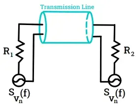
Then, we know that the power transferred from to , denoted , must equal the power transferred from to , . In addition, we know that
since we have a voltage divider over two resistors with equivalent resistance .
Thus, we have
where f is frequency.
We can now ask, how much energy is being transferred through the transmission line? If the transmission line has length l, and the power is being transferred at velocity v, then we have
The factor of two comes from the fact that there are two trains of energy passing through the transmission line: one from to , and the other traveling backwards. is the time it takes for the wave the propagate.
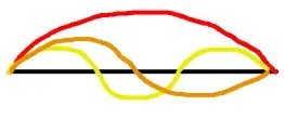
Instead of thinking about and as separate trains from to and to we can instead interpret the energy transfer from the resistors as standing electromagnetic waves across the transmission line such that where is the # of modes of the wave, is the wavelength, v is the velocity of propagation, and f is the associated frequency of the standing wave. Rearraging the equation yields We also note that for a given , we have modes. Note that there are actually two mediums of energy stored within the transmission line: electric energy and magnetic energy storage. The equipartition theorem dictates that each degree of freedom has an associated of energy, so we have
Setting equations and equal to each other yields